Orders may be delayed due to high order volumes and raw material delays
Resources

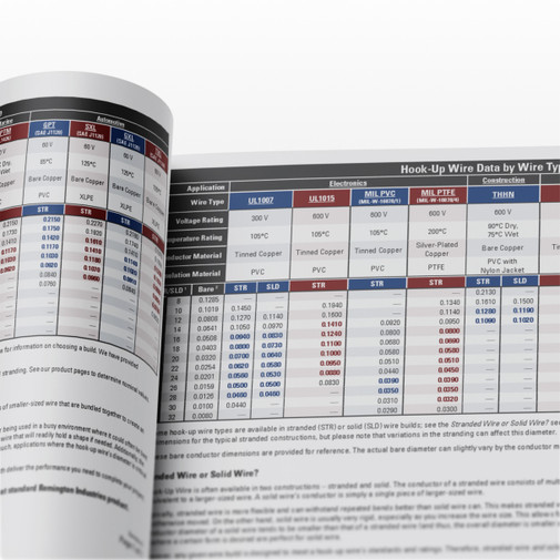
Wire Gauge Charts and Electrical References
Wire gauge charts are used to identify the relationship between a wire’s size, diameter, and electrical performance. Commonly referenced when selecting electrical wire, these charts help users compare wire gauge sizes, determine wire diameter, and understand how wire size relates to current capacity.
Electrical reference charts may include:
- Wire gauge charts showing AWG sizes and corresponding diameters
- Wire size charts comparing different gauges and physical dimensions
- Wire ampacity charts that indicate current-carrying capacity
- Electrical wire size charts used for general wiring applications
These references are essential when choosing wire for safety, performance, and compliance across electrical, automotive, marine, and industrial projects.
A good wire size chart provides a clear comparison of wire gauges, diameters, and electrical characteristics, making it easier to select the correct wire for a specific application.
These wire gauge charts can help you choose the most appropriate magnet wire, hook up wire and uninsulated wire from our online store.

Raw Metal Specifications
In addition to wire resources, this page also provides access to raw metal specifications for aluminum 6061 and stainless steel 304. Material specification data is commonly used to verify properties such as composition, dimensions, tolerances, and mechanical characteristics.
Raw metal specifications are especially important for:
- Machining and fabrication
- Manufacturing and prototyping
- Engineering and design validation
These resources support accurate material selection and help ensure consistency when working with aluminum, stainless steel, and other metal stock.
Additional Technical Resources
Additional technical references and specifications may be available to support specialized applications, cable assemblies, or accessories. These resources are intended to provide clarity, consistency, and reliable reference data across a wide range of electrical and material-related projects.

Understanding Wire Gauge and AWG Standards
AWG, or American Wire Gauge, is the standard system used to define the size of electrical wire in North America. In this system, a smaller gauge number indicates a larger wire diameter, while larger gauge numbers represent thinner wire.
AWG standards are commonly used to describe:
- Wire gauge sizes
- Bare conductor diameter
- Cross-sectional area
- Resistance and electrical characteristics
Understanding AWG is critical when interpreting a wire gauge chart, selecting compatible wire sizes, or comparing different types of copper wire. AWG charts are often referenced to confirm the actual size of a wire based on its measured diameter rather than its nominal label.
This type of resource may also be referred to as an actual size wire gauge chart.
By consulting an AWG wire size chart, users can verify conductor dimensions and better understand how different wire gauges compare in real-world measurements.

Wire Size, Ampacity, and Current Capacity
Ampacity refers to the maximum amount of electrical current a wire can safely carry. A wire ampacity chart or wire size amp chart helps users match wire gauge to current requirements while minimizing overheating and voltage drop.
When using ampacity references, it’s important to consider:
- Wire gauge and conductor size
- Installation environment
- Insulation type
- Application-specific conditions
Ampacity charts are commonly used alongside wire gauge charts to ensure proper wire selection for electrical systems, control wiring, and equipment connections.